User Guide🔗

Introduction🔗
The PAN9028 mSD-U adapter (ENWF9408AVEF) features a PAN9028 with an integrated Power Management IC (ENWF9408A1EF).
You can access the module SDIO and UART interfaces, which are required to connect the PAN9028 to a host processor. The adapter is ideally suited for the evaluation of the module in conjunction with host processor evaluation kits that have a micro SD card slot.
Features🔗
- Compact micro SD form factor
- UART interface pin header
- External power supply pin header
- External antenna U.FL connector
Block Diagram🔗

Board Overview🔗

1
The module
2
Bluetooth interface selection pin header
You can use the Bluetooth interface selection pin header to select the control interface for Bluetooth®. Also see Bluetooth Interface Configuration
3
Bluetooth UART pin header
You can use the Bluetooth UART pin header to connect the UART HCI interface to the host processor. Also see Connecting the UART Interface
4
Module power supply pin header
You can use the module power supply pin header to supply the module with power externally. Also see Module Power Options
5
Micro SD connector
You can insert the PAN9028 mSD-U adapter into a micro SD card slot.
6
Power LED
You can observe the power LED to verify that the board is correctly powered.
7
External antenna U.FL connector - X1
You can use the U.FL connector to connect an external antenna. Also see Antenna Configuration
Initial Preparations🔗
Before you can work with the PAN9028 mSD-U adapter you have to modify the adapter according to your requirements and your host system.
You can use the i.MX 8MQuad Evaluation Kit as a Linux® based host system. As a MCU based host system you can use the i.MX RT1170 Evaluation Kit.
Bluetooth Interface Configuration🔗
In case you want to operate the Bluetooth part of the module execute the following instructions to select UART as the host interface.
-
Solder a pin header into the Bluetooth interface configuration pads.

-
Place a jumper to bridge the BT pin 1 and the UART pin 2.

The Bluetooth UART pin header 3 is now configured as the host interface for Bluetooth (see Connecting the UART Interface).
Connecting the UART Interface🔗
The following requirements must be met:
- You have configured UART as the Bluetooth host interface as described in Bluetooth Interface Configuration.
- Your host system has an accessible UART interface including CTS/RTS flow control pins.
To connect the Bluetooth UART pin header 3 to your host system execute the following instructions.
-
Connect the TX 1 and RX 2 signals.

-
Connect the CTS 1 and RTS 2 flow control signals.

-
Establish a common ground connection with your host system.
UART Voltage Level
The voltage level used for the UART communication is defined by VIO. You can either set it to 3.3 V or to 1.8 V.
When using high speed UART (3 Mbaud) you have to configure VIO to 1.8 V to ensure the timing requirements are met.
For instructions on how to configure VIO please refer to IO Reference Voltage.
Module Power Options🔗
For power measurements or certification purposes you can supply the module with power using the module power supply pin header 4 instead of the VDD of the micro SD interface. Execute the following instructions to use the module power supply pin header.
-
Unsolder R3.

-
Place a 0 Ohm (0402) resistor for R2 or bridge it with a solder blob.

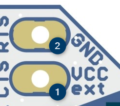
-
Connect the external 3.3 V power supply to VCCext 1 and GND 2 of the module power supply pin header 4.
Note
To get an accurate reading for the power measurement you have to remove the power LED 6 or the current limiting resistor R9.
SDIO Reference Voltage🔗
The PAN9028 supports 1-bit or 4-bit SDIO transfer modes with full clock range up to 208 MHz. The SDIO Interface pins are powered from the VIOSD voltage supply with either 3.3 V or 1.8 V.
On the PAN9028 mSD-U adapter by default VIOSD is connected to the VDD of the SDIO interface, hence it is set to 3.3 V. You can reconfigure the PAN9028 mSD-U adapter to use the 1.8 V generated by the PMIC as VIOSD to allow higher SDIO clock speeds to be used.
To configure the PAN9028 mSD-U adapter to use the 1.8 V of the PMIC as the voltage reference execute the following instructions.
-
Unsolder R12.

-
Place a 0 Ohm resistor (0402) for R13 or bridge it with a solder blob.

-
In case R14 is placed unsolder it.

Note
SDIO clock speeds higher than 50 MHz can only be achieved with a SDIO signal voltage level (VIOSD) of 1.8 V and a host processor that supports the SDIO 3.0 Standard.
The maximum achievable data rate is limited by the used SDIO clock speed.
For further information please refer to the module product specification at
IO Reference Voltage🔗
The voltage used by the IOs and the UART interface is determined by the voltage applied to VIO. You can configured it to either 3.3 V or 1.8 V.
On the PAN9028 mSD-U adapter by default VIO is connected to VDD of the SDIO connector, hence it is set to 3.3 V.
To set VIO to 1.8 V execute the following instructions.
-
Unsolder R4.

-
Place a 0 Ohm resistor (0402) for R11 or bridge it with a solder blob.

This connects VIO to the 1.8 V output of the PMIC.
Antenna Configuration🔗
You can configure the module to either use the chip antenna or the external antenna.
External Antenna🔗
To configure the external antenna U.FL connector X1 7 to be used execute the following instructions.
-
Unsolder R6.

-
Place a 0 Ohm resistor (0402) for R7 or bridge it with a solder blob.

Chip Antenna🔗
On the PAN9028 mSD-U adapter by default the chip antenna is selected. In case you modified the adapter to use the external antenna execute the following instructions to switch back to the chip antenna.
-
Unsolder R7

-
Place a 0 Ohm resistor (0402) for R6 or bridge it with a solder blob.
