i.MX 8MQuad EVK🔗
Introduction🔗
The PAN9028 requires a fairly powerful host processor that executes the low-level Wi-Fi® and Bluetooth® drivers as well as some high-level Wi-Fi application software and a Bluetooth stack.
As an evaluation platform you can use the i.MX 8MQuad Evaluation Kit (MCIMX8M-EVK), which is based on the i.MX 8MQuad application processor with four Arm® Cortex®-A53 cores and a Cortex-M4 core. It features a 4 GB LPDDR4 RAM, a 16 GB eMMC, Gigabit Ethernet, USB 3.0 and HDMI 2.0.
The i.MX 8MQuad supports the SDIO 3.0 specification, which is required for operation of the PAN9028.
Bluetooth Operation
The i.MX 8MQuad Evaluation Kit does not have an easily accessible UART interface that is required as host interface for Bluetooth.
Please refer to Serial Adapter Setup for information on how you can use a FTDI® USB-to-Serial adapter to connect the Bluetooth host interface.
For the i.MX 8MQuad Evaluation Kit a Linux® Board Support Package (BSP) is available from NXP. The Linux BSP provides everything that is needed to build a Linux-based image for the i.MX 8MQuad Evaluation Kit using the Yocto Project®.
Yocto Project
The Yocto Project is an open source project that provides templates, tools and methods for creating custom Linux images for embedded systems.
Chip and board vendors as well as the Linux community contribute to it by adding support for evaluation boards, processors, drivers and software packages in the form of so-called meta layers.
You can find an overview of the Linux BSP releases on the Embedded Linux for i.MX Application Processors page.
Under the section Linux Current Release you can find information and documentation regarding the latest BSP release. Including the following:
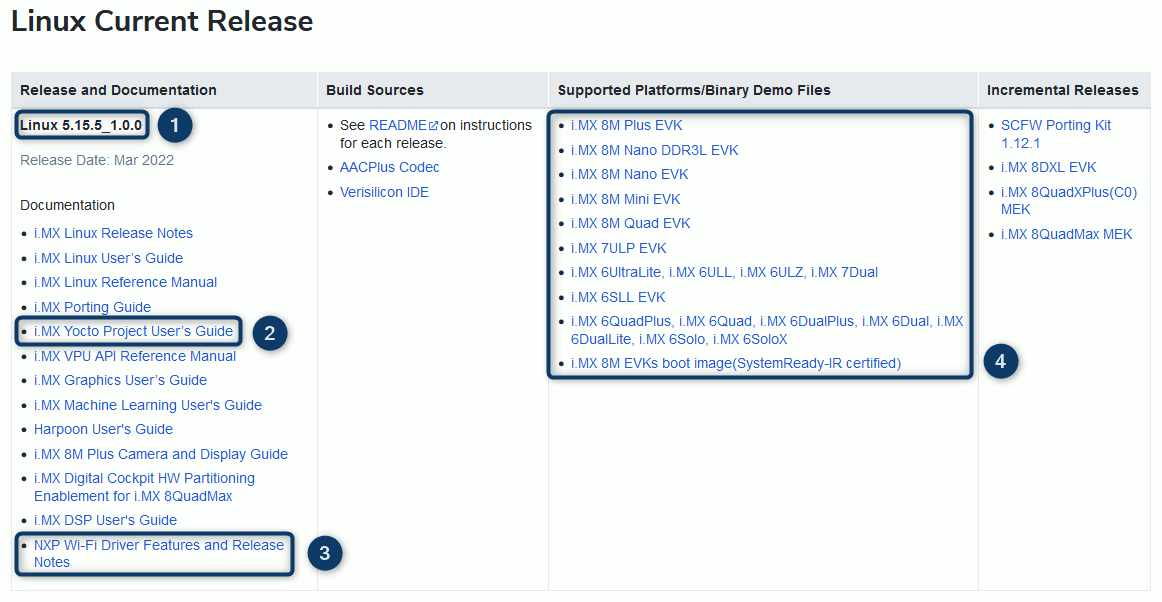
- The name of the release 1. In this case, Linux 5.15.5_1.0.0 with 5.15.5 being the Linux kernel version that is used.
- The i.MX Yocto Project User's Guide 2 documenting the build process of the Linux image with Yocto.
- The NXP Wi-Fi Driver Features and Release Notes 3.
- A list of the supported evaluation kits 4 based on processors from the i.MX application processor family.
Note
Please note that you need an account for the NXP Homepage to be able to access the mentioned documents.
Board Overview🔗

1
Micro SD card slot
You can insert the PAN9028 mSD-U adapter into the micro SD card slot.
2
USB debug port
You can use the USB debug port to interact with the operating system.
3
Boot mode switch - SW802
You can use the boot mode switch to select the boot mode. Also see Writing to the eMMC and Booting from the eMMC
4
Boot device switch - SW801
You can use the boot device switch to select the boot device. Also see Writing to the eMMC and Booting from the eMMC
5
Ethernet port
You can use the ethernet port to connect the i.MX 8MQuad Evaluation Kit to a wired network.
6
USB 3.0 port
You can use the USB 3.0 port to connect a USB-to-Serial adapter to the host system. Also see Serial Adapter Setup
7
12 V DC power input jack
You can use the 12 V DC power input jack to supply power to the board.
8
USB Type-C port
You can use the USB Type-C port to write to the eMMC. Also see Writing to the eMMC
9
Power switch
You can use the power switch to control the board power supply.
Host System Setup🔗
Building the Yocto Image🔗
The Linux BSP consists of a number of meta layers providing recipes for building packages that in sum make up the image for the i.MX 8MQuad Evaluation Kit. This includes the Linux kernel, a root filesystem and a bootloader. The Wi-Fi drivers are built as kernel modules.
A manifest file specifies the meta layers that the BSP is based on. The manifest files are hosted on the imx-manifest repository. The repo tool is used to manage the Git repositories of the different meta layers.
The Linux BSP is built upon the meta layers maintained by the FSL Community which provide support for i.MX boards in the Yocto Project. An additional meta-imx layer is used to release updated and new recipes and machine configurations that are eventually upstreamed to the community layers maintained by the community.
The following requirements must be met:
- You have a Linux based development machine set up for Yocto builds as described in the Host Setup chapter of the i.MX Yocto Project User's Guide.
- You have the repo tool installed on the development machine as described in the Host Setup chapter of the i.MX Yocto Project User's Guide.
-
Create a new folder
imx-yocto-bspfor the Linux BSP data.mkdir imx-yocto-bsp cd imx-yocto-bsp -
Initialize the current directory as a repo client directory.
repo init -u https://github.com/nxp-imx/imx-manifest -b imx-linux-honister -m imx-5.15.5-1.0.0.xmlThe
.repofolder is created.Newer Linux BSP version
The Linux BSP version you see here might be outdated and a new Linux BSP version might already be available.
Please check out the Linux Current Release table at Embedded Linux for i.MX Application Processors to find out the most recent Linux BSP version:

You can then go to the NXP
imx-manifestGit repository and verify that this version is available for the Yocto Linux version you plan to use.Not all Linux BSP versions are available for all Yocto Linux versions.
The Examples section of the i.MX Repo Manifest README usually lists all available Linux BSP versions for a specific Yocto Linux version in a particular branch.
-
Synchronize the local directory with the remote repositories.
repo syncThe latest revision of the meta layers is downloaded from the respective repositories and stored in the
sourcesdirectory. -
Execute the following command to setup the build directory and configuration files.
DISTRO=fsl-imx-wayland MACHINE=imx8mqevk source imx-setup-release.sh -b build -
You are prompted to read and accept an EULA by NXP. To continue to use the i.MX proprietary software, you must agree to the conditions of this license. Press Space to page through the EULA. At the end press Y to accept.
In case you accepted the EULA, the
builddirectory is created and set as the current working directory. -
In
build/conf/local.confadd the following line to include the devicetree compiler in the image.CORE_IMAGE_EXTRA_INSTALL += "dtc"This package is needed to later make the modifications of the devicetree described in Adjusting SDIO Voltage Level.
-
Start the Yocto build.
bitbake imx-image-multimediaOnce the build is done the compressed Linux image
imx-image-multimedia-imx8mqevk.wic.bz2and the bootloader used for writing to the eMMCimx-boot-imx8mqevk-sd.bin-flash_evkare available intmp/deploy/images/imx8mqevk.
Linux BSP Releases
The Linux BSP is released for a specific Yocto Project Release (in this case release 3.4 with the codename Honister) and a specific kernel version (in this case 5.15.5) used by that Yocto Release.
The releases of the drivers for the PAN9028 follow the release schedule of the Linux BSP.
To get an overview of the available releases you can check out Embedded Linux for i.MX Application Processors.
Note
The Linux BSP lets you choose from a number of distros, images and target machines.
For further information on the Linux BSP and the Yocto build process please refer to the i.MX Yocto Project User's Guide.
Writing to the eMMC🔗
Since the micro SD card slot 1 is occupied by the PAN9028 mSD-U adapter you need to use the eMMC as a boot medium. To write the Linux image to the eMMC you can use the Universal Update Utility.
The following requirements must be met:
- You have successfully built the Yocto image as described in Building the Yocto Image.
- You have installed the Universal Update Utility as described in the chapter Universal update utility of the i.MX Linux User's Guide.
Note
Please note that you need an account for the NXP Homepage to be able to access the mentioned documents.
| Boot Switch | D1 | D2 | D3 | D4 |
|---|---|---|---|---|
| SW8023 | OFF | ON | - | - |
| SW8014 | OFF | OFF | ON | OFF |
| Boot switch configuration for writing to the eMMC | ||||
Execute the following steps to write the image to the eMMC.
-
Configure the eMMC as the boot device by setting the boot device switch SW801 4 to the configuration listed in the table above.
-
Set the boot mode switch SW802 3 to the serial download setting as listed in the table above.
-
Connect both the USB debug port 2 and the USB Type-C port 8 to your computer.
-
Power on the i.MX 8MQuad Evaluation Kit with the power switch 9.
-
Execute the following command.
uuu -b emmc_all imx-boot-imx8mqevk-sd.bin-flash_evk imx-image-multimedia-imx8mqevk.wic.bz2The Universal Update Utility first downloads the bootloader and afterwards decompresses and writes the image to the eMMC.
Booting from the eMMC🔗
The following requirement must be met:
- You have written the Linux image to the eMMC as described in Writing to the eMMC.
| Boot Switch | D1 | D2 | D3 | D4 |
|---|---|---|---|---|
| SW8023 | ON | OFF | - | - |
| SW8014 | OFF | OFF | ON | OFF |
| Boot switch configuration for booting from the eMMC | ||||
Execute the following steps to boot the i.MX 8MQuad Evaluation Kit from the eMMC.
-
Configure the eMMC as the boot device by setting the boot device switch SW801 4 to the configuration listed in the table above.
-
Set the boot mode switch SW802 3 to the internal boot setting as listed in the table above.
-
Power on the i.MX 8MQuad Evaluation Kit with the power switch 9.
Once the system has finished booting, you can interact with it using the USB debug port 2 via a serial console (115200 baud) or using SSH if the i.MX 8MQuad Evaluation Kit is connected to a network via the Ethernet port 5.
Serial Console / SSH
If you do not have any SSH application yet, you can try PuTTY.
Adjusting SDIO Voltage Level🔗
Note
The modification of the mmc1 node in the devicetree is only required if the PAN9028 mSD-U adapter is used with the SDIO voltage configured to 3.3 V.
In case the SDIO voltage is configured to 1.8 V as described in SDIO Reference Voltage the steps described in this subsection can be skipped.
The host system attempts to switch from an initial SDIO signal voltage level of 3.3 V to 1.8 V after the PAN9028 mSD-U adapter is inserted into the micro SD card slot. In the default configuration of the PAN9028 mSD-U adapter this leads to errors, since the adapter is configured to work with 3.3 V SDIO voltage levels only.
The following requirements must be met:
- You have built the Yocto image as described in Building the Yocto Image.
- You have written the image to the eMMC as described in Writing to the eMMC.
Execute the following steps to add the no-1-8-v property to the mmc1 node of the devicetree, which prevents the host system from attempting to switch the SDIO voltage level.
-
Boot up the Linux image on the i.MX 8MQuad Evaluation Kit (see Booting from the eMMC).
-
On the running system enter the following command to add the
no-1-8-vproperty to themmc1node.fdtput /run/media/mmcblk0p1/imx8mq-evk.dtb mmc1 no-1-8-v -
Enter the following command to reboot the system.
rebootAfter the reboot the modification takes effect.
Note
If the SDIO voltage level is configured to 3.3 V the SDIO clock speed is limited to 50 MHz, which in term limits the maximum achievable Wi-Fi throughput.
Please refer to SDIO Reference Voltage for instructions on how to modify the PAN9028 mSD-U adapter to work with 1.8 V voltage levels.
Driver Concepts🔗
The following sections give an conceptional overview of the Wi-Fi and Bluetooth drivers.
Wi-Fi Driver🔗
The PAN9028 requires a kernel driver loaded on the host system and a firmware running on the module.

The Wi-Fi driver consists of two kernel modules mlan.ko and moal.ko.
The firmware binary is downloaded by the mlan module onto the wireless module once the SDIO bus driver detects the PAN9028. The moal module is loaded between the SDIO bus driver and the network stack of the CFG80211 subsystem in the kernel.
The network interfaces of the PAN9028 are available in the user space in the form of Netlink sockets. The user space applications hostapd, wpa_supplicant and iw control the Wi-Fi device.
For instructions on how to load the Wi-Fi driver kernel modules please refer to Loading the Kernel Modules.
The Wi-Fi driver is developed by NXP and released on GitHub. It is integrated in the Linux BSP in form of the recipes kernel-module-nxp89xx.bb and nxp-wlan-sdk_git.bb in the meta-imx layer.
The firmware binary (sdiouart8987_combo_v0.bin) is released as part of the imx-firmware repository. It is integrated in the Linux BSP with the linux-firmware_%.bbappend file (meta-imx) which provides various additions to the linux-firmware package.
Note
For further information please refer to the user manual UM11483 - Getting Started with NXP-based Wireless Modules on i.MX 8M Quad EVK Running Linux OS, which is available under the Documentation section on the 88W8987 product page.
Please note that you need an account for the NXP Homepage to be able to access this document.
Bluetooth Driver🔗
The hci_uart driver provides the UART HCI interface between the firmware and the user application.

It is developed as part of the Linux kernel and can be activated in the kernel configuration by setting CONFIG_BT_HCIUART=y to compile it into the kernel or CONFIG_BT_HCIUART=m to build it as a kernel module.
The combo firmware binary contains the Wi-Fi as well as the Bluetooth firmware and is loaded into the PAN9028 by the Wi-Fi driver (see Wi-Fi Driver).
In the i.MX Linux BSP hci_uart is compiled into the kernel by default. The BlueZ Bluetooth stack is the standard Bluetooth stack on Linux systems and runs in user space.
Note
For further information please refer to the user manual UM11483 - Getting Started with NXP-based Wireless Modules on i.MX 8M Quad EVK Running Linux OS, which is available under the Documentation section on the 88W8987 product page.
Please note that you need an account for the NXP Homepage to be able to access this document.
Wi-Fi Operation🔗
The following sections describe how to install the Wi-Fi drivers and the basics of the Wi-Fi operation.
Loading the Kernel Modules🔗
After booting the Linux system on the i.MX 8MQuad Evaluation Kit the Wi-Fi drivers are not loaded into the kernel yet. Since the Wi-Fi drivers are built as out-of-tree modules, you have to manually load them into the kernel prior to operation.
To load the required kernel modules execute the following instructions.
-
Edit the
SD8987section in/lib/firmware/nxp/wifi_mod_para.confto contain the following settings.... SD8987 = { cfg80211_wext=0xf cal_data_cfg=none drv_mode=3 fw_name=nxp/sdiouart8987_combo_v0.bin } ... -
You might have to add country-specific configuration settings. This depends on where you are going to run this setup.
Energy Detection Feature
If you intend to use the PAN9028 module in the EU, you have to assure that the energy detection feature is enabled and you have to provide the correct configuration settings.
Add the following setting to the
SD8987section in/lib/firmware/nxp/wifi_mod_para.conf./lib/firmware/nxp/wifi_mod_para.confUnfortunately, the configuration file does not come pre-installed with the driver. Refer to Energy Detection Configuration File to learn how to provide this file correctly.... SD8987 = { ... init_hostcmd_cfg=nxp/ed_mac_ctrl_V3_8987.bin } ...For USA and Canada no country-specific configuration settings are necessary.
Note
Please contact your local Panasonic Sales office for details on additional product options and services.
If you intend to use the PAN9028 module in multiple regions, you have to use the same configuration as in the case for the EU.
This is mainly because the EU has some of the strictest regulatory standards, and if you use the appropriate configuration this ensures compliance with these requirements.
Add the following setting to the
SD8987section in/lib/firmware/nxp/wifi_mod_para.conf./lib/firmware/nxp/wifi_mod_para.confUnfortunately, the configuration file does not come pre-installed with the driver. Refer to Energy Detection Configuration File to learn how to provide this file correctly.... SD8987 = { ... init_hostcmd_cfg=nxp/ed_mac_ctrl_V3_8987.bin } ... -
Load the
mlankernel module.insmod /lib/modules/$(uname -r)/extra/mlan.ko -
Load the
moalkernel module.insmod /lib/modules/$(uname -r)/extra/moal.ko mod_para=nxp/wifi_mod_para.conf -
Insert the PAN9028 mSD-U adapter into the micro SD card slot 1. You should see the following kernel messages.
Request firmware: nxp/sdiouart8987_combo_v0.bin
Wlan: FW download over, firmwarelen=579384 downloaded 579384
WLAN FW is active
...
call regulatory_set_wiphy_regd US
ForceRegionRule is set in the on-chip OTP memory
11D: Error setting domain info in FW
The messages indicate that the firmware download was successful. The application environment made an attempt to set the country code for the device, but since the PAN9028 has already a country code with the according power limits stored on the device itself this attempt fails.
-
Execute the following command to check if the Wi-Fi interfaces have been created.
ip addr
...
3: mlan0: <BROADCAST,MULTICAST> mtu 1500 qdisc noop state DOWN group default qlen 1000
    link/ether 00:13:43:cb:70:a1 brd ff:ff:ff:ff:ff:ff
4: uap0: <BROADCAST,MULTICAST> mtu 1500 qdisc noop state DOWN group default qlen 1000
    link/ether 00:13:43:cb:71:a1 brd ff:ff:ff:ff:ff:ff
The
mlan0(station) anduap0(access point) interfaces are now available.
Note
For further information please refer to the user manual UM11483 - Getting Started with NXP-based Wireless Modules on i.MX 8M Quad EVK Running Linux OS, which is available under the Documentation section on the 88W8987 product page.
Please note that you need an account for the NXP Homepage to be able to access this document.
Connecting to an Access Point🔗
The following requirement must be met:
- You have loaded the Wi-Fi kernel modules as described in section Loading the Kernel Modules.
When connecting the PAN9028 to an access point the module will act as a so-called Wi-Fi station. To connect the station to an access point with WPA2 security you have to execute the following steps.
-
Create the file
/etc/wpa_supplicant.confwith the following content. Adjust thessidandpsksettings to match your Wi-Fi network settings.ctrl_interface=/var/run/wpa_supplicant ctrl_interface_group=0 update_config=1 ap_scan=1 network={ ssid="Demo_AP" key_mgmt=WPA-PSK proto=RSN pairwise=CCMP group=CCMP psk="123456789" } -
Start the
wpa_supplicantwith the previously created configuration.wpa_supplicant -i mlan0 -Dnl80211 -c /etc/wpa_supplicant.conf -B -
To check the connection status execute the following command.
wpa_cli statusThe output should look something like this:
Selected interface 'mlan0'
bssid=xx:xx:xx:xx:xx:xx
freq=2437
ssid=Demo_AP
id=0
mode=station
pairwise_cipher=CCMP
group_cipher=CCMP
key_mgmt=WPA2-PSK
wpa_state=COMPLETED
p2p_device_address=00:13:43:cb:70:a1
address=00:13:43:cb:70:a1
uuid=3444e0ea-b920-5afb-94ec-7f32301f4771
If the
wpa_statusisCOMPLETEDthe connection to the network was successfully established. -
Start the DHCP client to automatically obtain an IP address.
udhcpc -i mlan0
Note
For further information please refer to the user manual UM11490 - Feature Configuration Guide for NXP-based Wireless Modules on i.MX 8M Quad EVK, which is available under the Documentation section on the 88W8987 product page.
Please note that you need an account for the NXP Homepage to be able to access this document.
Starting the Access Point🔗
The following requirement must be met:
- You have loaded the Wi-Fi kernel modules as described in section Loading the Kernel Modules.
To configure and start an access point with WPA2 in the 2.4 GHz band you have to execute the following steps.
-
Create the file
/etc/hostapd.confwith the following content forhostapd.interface=uap0 hw_mode=g channel=6 ssid=Demo_uAP ieee80211n=1 auth_algs=1 wpa=2 wpa_key_mgmt=WPA-PSK rsn_pairwise=CCMP wpa_passphrase=123456789 -
Create the file
/etc/udhcpd.confwith the following content forudhcpd.start 192.168.1.10 end 192.168.1.10 interface uap0 -
Make sure the file for tracking DHCP leases exists.
touch /var/lib/misc/udhcpd.leases -
Bring up the
uap0interface.ip link set dev uap0 up -
Assign an IP address and netmask to the
uap0interface.ip addr add 192.168.1.1/24 dev uap0 -
Start the DHCP server with the previously created configuration.
udhcpd /etc/udhcpd.conf -
Start
hostapdwith the previously created configuration.hostapd /etc/hostapd.conf -BThe output should look something like this:
rfkill: Cannot open RFKILL control device
Using interface uap0 with hwaddr 00:13:43:cb:71:a1 and ssid "Demo_uAP"
uap0: interface state UNINITIALIZED->ENABLED
uap0: AP-ENABLED
As indicated by the messages the access point has been initialized and is up and running.
Note
For further information please refer to the user manual UM11490 - Feature Configuration Guide for NXP-based Wireless Modules on i.MX 8M Quad EVK, which is available under the Documentation section on the 88W8987 product page.
Please note that you need an account for the NXP Homepage to be able to access this document.
Bluetooth Operation🔗
The following sections describe how to bring up the Bluetooth device and the basics of the Bluetooth Low Energy operation.
Serial Adapter Setup🔗
Since the i.MX 8MQuad Evaluation Kit is missing an easily accessible UART interface with RTS and CTS pins you need to use an USB-to-Serial adapter for connecting the Bluetooth host interface.
FTDI based USB-to-Serial adapters are supported by the ftdi_sio driver in the Linux kernel.
The following requirements must be met:
- You have a FTDI based USB-to-Serial adapter at your disposal.
- You have set
CONFIG_USB_SERIAL_FTDI_SIO=yin the kernel configuration (this is the case by default). - You have configured the Bluetooth host interface to UART as described in Bluetooth Interface Configuration.
To set up the UART connection with a USB-to-Serial adapter you have to execute the following steps.
-
Configure the signal voltage level of the USB-to-Serial adapter to match the setting of VIO (see IO Reference Voltage). The default configuration is 3.3 V.
-
Connect the RX, TX, CTS and RTS signals and ground as described in Connecting the UART Interface with the USB-to-Serial adapter using jumper cables.
-
Insert the USB-to-Serial adapter into the USB 3.0 port 6.
The serial USB device shows up as
/dev/ttyUSBx.
Bring Up🔗
The following requirements must be met:
- You have connected the UART interface as described in Serial Adapter Setup.
- You have loaded the Wi-Fi kernel modules as described in section Loading the Kernel Modules.
To bring up the Bluetooth interface you have to execute the following steps.
-
In case you have modified the kernel configuration to build the
hci_uartdriver as a module (CONFIG_BT_HCIUART=m) load the module by executing the following command. Otherwise skip this step.modprobe hci_uart -
Attach the UART HCI device to the BlueZ stack by executing the following command.
hciattach /dev/ttyUSBx any 3000000 flow -
Bring up the
hci0interface.hciconfig hci0 up -
To check the status of the
hci0interface execute the following command.hciconfigThe output should look something like this:
hci0:   Type: Primary  Bus: UART
      BD Address: 00:13:43:CB:70:A2  ACL MTU: 1016:5  SCO MTU: 60:12
      UP RUNNING
      RX bytes:1456 acl:0 sco:0 events:86 errors:0
      TX bytes:1238 acl:0 sco:0 commands:86 errors:0
The
hci0device is ready for operation.
Note
For further information please refer to the user manual UM11490 - Feature Configuration Guide for NXP-based Wireless Modules on i.MX 8M Quad EVK, which is available under the Documentation section on the 88W8987 product page.
Please note that you need an account for the NXP Homepage to be able to access this document.
Running a Scan🔗
The following requirement must be met:
- You have brought up the
hci0interface as described in Bring Up.
To run a Bluetooth scan for Low Energy devices execute the following steps.
-
Start the interactive
bluetoothctltool by executing the following command.bluetoothctlThe output should look something like this:
Agent registered [CHG] Controller 00:13:43:CB:70:A2 Pairable: yes -
Execute the following commands in the interactive shell. The interactive shell is prefixed with
[bluetooth]#. -
Start the Bluetooth scan by entering the following command.
scan on -
The tool outputs any discovered devices.
Discovery started [CHG] Controller 00:13:43:CB:70:A2 Discovering: yes [NEW] Device 00:13:43:C0:FF:EE test_device -
To stop the scan enter the following command.
scan off -
You can list all discovered and previously connected devices enter the following command.
devicesThe output should look something like this:
Device 00:13:43:C0:FF:EE test_device
Note
For further information please refer to the user manual UM11490 - Feature Configuration Guide for NXP-based Wireless Modules on i.MX 8M Quad EVK, which is available under the Documentation section on the 88W8987 product page.
Please note that you need an account for the NXP Homepage to be able to access this document.
Connecting to a Device🔗
The following requirement must be met:
- You have run a Bluetooth Low Energy scan as described in Running a Scan.
To pair and connect to a Low Energy device execute the following steps in the bluetoothctl interactive shell which is prefixed with [bluetooth]#.
-
Register an agent by entering the following command.
agent onThe output should look something like this:
Agent registered [CHG] Controller 00:13:43:CB:70:A2 Pairable: yes -
Choose the
default-agentby entering the following command.default-agentThe output should look something like this:
Default agent request successfulThe agent is responsible for handling the pairing procedure.
-
Start the pairing procedure.
pair 00:13:43:C0:FF:EEThe output should look something like this:
Attempting to pair with 00:13:43:C0:FF:EE [CHG] Device 00:13:43:C0:FF:EE Connected: yes -
Type
yesto confirm the passkey if the the agent prompts you to do so.Request confirmation [agent] Confirm passkey 123456 (yes/no): yesThe pairing is completed once you have confirmed the pairing request on the other device as well.
-
Add the device to the trusted devices.
trust 00:13:43:C0:FF:EEThe output should look something like this:
Changing 00:13:43:C0:FF:EE trust succeededTrusting the device speeds up future connection attempts.
-
Connect to the device with the following command.
connect 00:13:43:C0:FF:EE -
You can disconnect from the device by entering the following command.
disconnect 00:13:43:C0:FF:EE -
You can remove the device from the list of paired devices enter the following command.
remove 00:13:43:C0:FF:EE -
To exit
bluetoothctlenter the following command.quit
Pairing Procedure
Depending on the configuration and capabilities of the Bluetooth Low Energy device that you are using to connect to, the pairing procedure may differ from the one described above.
Note
For further information please refer to the user manual UM11490 - Feature Configuration Guide for NXP-based Wireless Modules on i.MX 8M Quad EVK, which is available under the Documentation section on the 88W8987 product page.
Please note that you need an account for the NXP Homepage to be able to access this document.
Addendum🔗
Energy Detection Configuration File🔗
In order to enable the energy detection function in the hardware correctly, a configuration is necessary. The Linux kernel driver requires a binary configuration file, but the driver package from NXP only comes with a textual configuration file.
You can either use a pre-configured version from the Downloads section or convert your own version.
Using the Pre-Configured Version🔗
You can download the pre-configured binary configuration file from the Downloads section.
-
Under Windows you can calculate the hash value of the file and verify the authenticity.
Get-FileHash -Algorithm SHA256 .\ed_mac_ctrl_V3_8987.bin Algorithm Hash --------- ---- SHA256 A8F0784F9DA7E70101930589A8946312513770AE79F997926DB45A9C7A99BAC9 -
Under Linux you can also calculate the hash value of the file and verify the authenticity.
sha256sum ed_mac_ctrl_V3_8987.bin a8f0784f9da7e70101930589a8946312513770ae79f997926db45a9c7a99bac9 ed_mac_ctrl_V3_8987.bin -
On the host system, copy the file to the designated directory so that the Linux kernel driver finds it.
cp ed_mac_ctrl_V3_8987.bin /lib/firmware/nxp/The binary configuration file for the energy detection mechanism is now provided correctly.
Manual Conversion🔗
The following requirement must be met:
- You need a PC running a recent Linux operating system, for example Ubuntu 22.04.
You can do a manual conversion of the official textual configuration file. For this task, NXP provides a tool called mlanutl that you can use.
-
Retrieve the official NXP firmware repository using Git. Make sure to select the latest branch or the branch you are currently using.
git clone -b lf-6.6.3_1.0.0 --single-branch https://github.com/nxp-imx/imx-firmware -
Retrieve the official NXP driver repository using Git.
git clone -b lf-5.15.52_2.1.0 --single-branch https://github.com/nxp-imx/mwifiexNote
The latest version of the
mlanutltool is only available in thelf-5.15.52_2.1.0branch of this repository. -
Compile the
mlanutlutility.cd mwifiex/mxm_wifiex/wlan_src/mapp/mlanutl/ make -
Use the
mlanutlto do the conversion of the official textual conversion file../mlanutl mlan0 hostcmd ../../../../../imx-firmware/nxp/FwImage_8987/ed_mac_ctrl_V3_8987.conf generate_raw ed_mac_ctrl_V3_8987.bin -
Verify the authenticity of the file by calculating the checksum.
sha256sum ed_mac_ctrl_V3_8987.bin
a8f0784f9da7e70101930589a8946312513770ae79f997926db45a9c7a99bac9  ed_mac_ctrl_V3_8987.bin
The checksum of this file and the pre-configured file from the Downloads section match.
-
Copy the file to the designated directory so that the Linux kernel driver finds it.
cp ed_mac_ctrl_V3_8987.bin /lib/firmware/nxp/The binary configuration file for the energy detection mechanism is now provided correctly.