User Guide🔗

The PAN1326C2 evaluation board (ENW89823AXKF) features a PAN1326C2 dual-mode Bluetooth® module which is based on the Texas Instruments CC2564C single-chip controller.

The PAN1316C evaluation board (ENW89823CXKF) features a PAN1316C dual-mode Bluetooth® module which is based on the Texas Instruments CC2564C single-chip controller.
A PULSE W1030 antenna and a micro coax cable are included.
Introduction🔗
The CC2564C single-chip controller on the PAN1326C2 and PAN1316C modules needs a host controller running a Bluetooth stack to operate.
You can connect the evaluation board to a PC using the USB-C connector to access the UART interface or stack the evaluation board as an Arduino shield to a compatible host controller board. Your choice!
This makes the evaluation board ideally suited for the evaluation of the modules and rapid prototyping of products.
Features🔗
- Arduino shield interface
- FTDI USB to UART Interface
- UART accessible via pin headers
- PCM audio interface accessible via pin headers
- Dedicated shutdown button
- 32kHz slow clock
- 1.8 V to 3.3 V level shifter
Block Diagram🔗

Board Overview🔗

1
USB connector
You can use the USB connector to power the board and gain access to the UART communication.
2
UART module connection pin header - P4
You can use the UART module connection pin header to directly communicate with the module's UART interface. Also you can disconnect the FTDI chip from the module by removing the jumpers to avoid conflicts when you use the Arduino pin header for UART communication.
3
First module power supply configuration pin header - P3
You can configure the power supply of the module here. Also see Module Power Supply
4
Second module power supply configuration pin header - P1
You can configure the power supply of the module here. Also see Module Power Supply
5
The module
6
U.FL connector - X1
You can connect an external antenna here (PAN1316 evaluation board only)
7
Arduino pin headers - P6, P9, P11, P14
You can use Arduino pin headers to attach to Arduino shields or boards. Also see Arduino Interface
8
Arduino power selection pin header - P10
You can use this pin header to select if the evaluation board is powered using 3.3V or 5V when used as an Arduino shield.
9
Audio connection pin header - P2
You can use the audio connection pin header to connect to the audio pins of the CC2564C chipset.
10
Shutdown button - S1
You can use the shutdown button to reset the board to a known-good state.
Initial Preparations🔗
Before you can work with the evaluation tool (again) you may have to check (or restore) the default jumper configuration or install device drivers, depending on the operating system you are using.
Default Jumper Configuration🔗
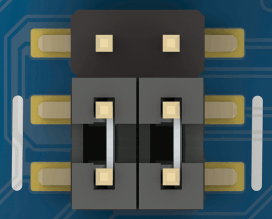
You can check the default jumper configuration easily because it is imprinted with white (or blue) line markings on the silkscreen of the PCB.
For example, the default jumper configuration in the following picture is:
- One jumper put on the lower left two pins
- One jumper put on the lower right two pins
FTDI USB UART Driver🔗
You may have to install a driver for the FTDI USB UART if the operating system you are using does not provide one automatically.
If in doubt, please refer to the FTDI website and install the drivers manually. For further information please refer to FTDI Driver Page.
Pin Map🔗
You can find information here about the interfaces that are not explained in more detail elsewhere in this guide.
| Header | Item | Group | Function | Module Footprint | Module Pin |
|---|---|---|---|---|---|
| P4 | 2 | UART | TX | 6 | HCI_TX |
| RX | 5 | HCI_RX | |||
| RTS | 4 | HCI_RTS | |||
| CTS | 3 | HCI_CTS | |||
| P2 | 9 | Audio | Sync | 7 | AUD_FSYNC |
| Clock | 19 | AUD_CLK | |||
| Input | 18 | AUD_IN | |||
| Output | 17 | AUD_OUT | |||
| S1 | 10 | Shutdown | Shutdown | 16 | NSHUTD |
For more information you can always check out the PAN1326C2 Product Specification at
Powering Options🔗
You can power the evaluation board in different ways:
USB Connector🔗
You can power the whole evaluation board using the USB connector 1.
You should use this method when you want to attach the evaluation board to a PC, but not when you want to use the evaluation board as an Arduino shield.
Arduino Pin Header🔗
You can power the whole evaluation board using the Arduino pin headers P6, P9, P11, P14 7 when you want to use the evaluation board as an Arduino shield together with a host controller board.
In this case do not attach the USB connector 1 simultaneously.
Both the 3.3 V and the 5 V pins are connected, however you have to follow these recommendations and set the Arduino power selection pin header P10 8 accordingly.

By default only the jumper that connects the 3.3 V support from the host controller board to the evaluation board is populated which is completely sufficient.
If you want to use the 5 V support from the host controller instead, just move over the jumper to the lower position, but do not populate both jumpers simultaneously. You are only allowed to either connect the 3.3 V support or the 5 V support at any time.
Risk of damaging board components
At all times do not supply 5 V on the 3.3 V pin of the Arduino pin headers P6, P9, P11, P14 7.
Arduino Interface🔗
You can use the Arduino interface on the Arduino Arduino pin headers P6, P9, P11, P14 7 to stack the evaluation board with boards that have an Arduino shield connector.
Upper Arduino Connector🔗
You can check the details of the pin mappings between the evaluation board and the module for the upper Arduino connector in the following table:
| Arduino Pin | Function | Module Footprint | Module Pin |
|---|---|---|---|
| SCL | Not connected | ||
| SDA | Not connected | ||
| AREF | Not connected | ||
| GND | Ground | ||
| D13 | Not connected | ||
| D12 | Not connected | ||
| D11 | Not connected | ||
| D10 | Not connected | ||
| D9 | Not connected | ||
| D8 | Not connected | ||
| D7 | Not connected | ||
| D6 | Not connected | ||
| D5 | Not connected | ||
| D4 | NRST | 16 | NSHUTD |
| D3 | UART CTS | 3 | HCI_CTS |
| D2 | UART RTS | 4 | HCI_RTS |
| D1 | UART RX | 5 | HCI_RX |
| D0 | UART TX | 6 | HCI_TX |
Lower Arduino Connector🔗
You can check the details of the pin mappings between the evaluation board and the module for the lower Arduino connector in the following table:
| Arduino Pin | Function | Module Footprint | Module Pin |
|---|---|---|---|
| NC | Not connected | ||
| IOREF | Not connected | ||
| NRST | Not connected | ||
| 3V3 | 3.3 V Power input | ||
| 5V | 5 V Power input | ||
| GND | Ground | ||
| GND | Ground | ||
| VIN | Not connected | ||
| A0 | Not connected | ||
| A1 | Not connected | ||
| A2 | Not connected | ||
| A3 | Not connected | ||
| A4 | Not connected | ||
| A5 | Not connected | ||
Note
The NSHUTDOWN signal of the module is not connected directly to the NRST pin of the Arduino header, but to the D4 pin instead.
The main reason is the different usage of the NRST signal by the Arduino which is incompatible to the way NSHUTDOWN works.
Module Power Supply🔗
You can configure the power supply of the PAN1326C2 module for different use-cases.
You can find the pros and cons of the different configurations in section Device Power Supply in the PAN1326C2 Product Specification at
Risk of Damage
You always have to configure the first module power supply configuration pin header P3 3 and the second module power supply configuration pin header P1 4 simultaneously.
You can damage the evaluation board if you use an incorrect configuration and accidentally short the different power domains.
For the use-case case Maximum RF output power, but not optimum system power you have to use the following configuration:

This is the default configuration.
For the use-case case Lower RF output power, but optimum system power you have to use the following configuration:

For the use-case case Maximum RF output power and optimum system power you have to use the following configuration:

Software Development🔗
The CC2564C single-chip controller on the PAN1326C2 and PAN1316C modules needs a host controller running a Bluetooth stack to operate.
Initial Testing🔗
When you attach the evaluation board to a regular PC an additional COM port appears. For an initial test you can communicate with the module manually and for example send a reset command to check if the communication is basically working.
Open the COM port with a terminal application of your choice that supports sending binary data, using a 115200,8,n,1,RTS/CTS flow control configuration. Using flow control is mandatory.
If you send the byte sequence 01 03 0c 00 which is the so-called HCI Reset command you should receive the answer 04 0E 04 01 03 0C 00 from the module.
You can use the HTerm terminal application for this purpose.
-
Set the serial port configuration to 115200,8,n,1 1

-
Open the serial port the evaluation board is connected to 2

-
Make sure that flow control is activated 3

-
Configure hexadecimal input and output 4

-
Enter the HCI Reset command in binary form as
01 03 0c 00and press Enter 5
The module responds with
04 0E 04 01 03 0C 006
Using a Linux System🔗
You can use a Linux system that supports USB to evaluate the evaluation board, for example Ubuntu 22.04.3 LTS running on a PC.
On such a system, Bluetooth support is provided by the BlueZ package.
Superuser / root privileges
You likely need superuser or root privileges for most of the operations that follow.
If in doubt and an operation fails, retry as the superuser, for example using sudo.
Prerequisites🔗
-
Make sure that everything is up-to-date and that
bluezin installed.apt update apt install bluez -
Find out which virtual COM port is assigned to the evaluation board when it is attached to your system.
Execute the following command and then attach the evaluation board to your system to retrieve some diagnostic information.
udevadm monitor -uThe output should look something like this:
[...]
UDEV  [84.497607] add      /devices/pci[...]/ttyUSB0 (usb-serial)
[...]
From the output you can see that
ttyUSB0is the virtual COM port that is assigned to the evaluation board. -
All CC2564C devices need a so-called init script or service pack to be uploaded before the device can be actually used.
Go to TI's webpage that provides Bluetooth service packs for all devices, download the file TIInit_6.12.26.bts and store it in a well-known location, for example the/tmp/directory for later use. -
Copy the file to the system-wide firmware directory for TI firmware files.
cp -i /tmp/TIInit_6.12.26.bts /lib/firmware/ti-connectivity/
Problem Description🔗
At this point you would usually use the hciattach tool to attach the virtual COM port from the evaluation board to the Linux Bluetooth stack:
$ hciattach /dev/ttyUSB0 texas 115200
[...]
Cannot send hci command to socket: Connection timed out
Can't initialize device: Connection timed out
Unfortunately there is a bug in all the recent versions of BlueZ that prevents a successful initialization.
For now, you have to patch BlueZ, compile the hciattach tool from the source code and use that local version instead of the one that comes with your distribution.
Compile from Source Code🔗
-
Install all build dependencies for BlueZ.
apt build-dep bluez -
Clone the BlueZ Git repository and prepare the build.
git clone https://github.com/bluez/bluez.git cd bluez ./bootstrap ./configure --enable-deprecated -
Download the patch from the Downloads section to a well-know location, for example the
/tmp/directory. -
Apply the patch to the BlueZ Git repository.
git am /tmp/0001-tools-hciattach-Increase-timeout-for-TI-specific-ini.patch -
Start the compilation.
make
Usage🔗
Now you can use the newly compiled hciattach tool to initialize the PAN1326C2 module on the evaluation board correctly.
Shutdown / Reset Button
Once you have initialized the PAN1326C2 module it goes into a different internal state.
If you want to re-initialize it, make sure to press the shutdown button S1 10 button to bring the PAN1326C2 module into a well-known state again.
tools/hciattach -n /dev/ttyUSB0 texas 115200
Found a Texas Instruments' chip!
Firmware file : /lib/firmware/ti-connectivity/TIInit_6.12.26.bts
Loaded BTS script version 1
texas: changing baud rate to 3000000, flow control to 1
Device setup complete
Now you can use all the regular BlueZ tools like bluetoothctl to communicate with the PAN1326C2 module on the evaluation board.